 Setting up a new tank to breed my plecos meant having to buy new lights, heaters, and filters. While browsing Amazon for a highly rated yet economical aquarium heater, I found myself staring at countless nightmarish reports of heaters overheating resulting in tanks full of dead livestock. Now for me, I have tanks set up and running at home where I am home only occasionally, and even though many of the heaters I use are trusted brands such as the inline Hydor ETH 201 and Eheim Jager, there are still enough accounts of them failing to make me nervous. Over time due to heat, use, and even just bad quality control, the internal thermostat in aquarium heaters may inevitably fail.
You can adjust the values to suit your purposes. For ten minutes of my time and twelve dollars, this temperature regulator setup offers me the peace of mind that my tanks have a fail safe and may one day save me hundreds of dollars in time and money. Worth it? Definitely.
After a bit of research, I discovered that there are off the shelf temperature controllers that are cheap and easy to use. If you search “temperature controller” or “temperature regulator” on Ebay you’ll find an abundance of these controllers with 12V, 110V, and 220V versions. The one I bought is slightly more expensive because it displays the temperature in Fahrenheit while the majority of the other models display in Celsius.
These temperature controllers are more commonly used by home brewers who need to keep their concoctions at specific temperatures and people who raise livestock, like chickens, to keep the coops heated during the winter without running the risk of being greeted by nestled rotisserie chickens the next morning. That being said, these controllers can only regulate one load (heater, lamp, etc.). They also sell models that can regulator 2 loads (a heating circuit and a cooling circuit). An example of a non-Chinese knockoff would be the STC-1000 All-Purpose Temperature Controller, which can be found on Amazon. An ABS plastic housing can also be found on Amazon which make sthe unit much more presentable.
Now, I’m no engineer but I’m no stranger to DIY electronics either, so I will try to explain the steps as clearly as possible.
Step 1: Materials
 Gather the following: Phillips head screwdriver, Temperature controller, Flathead screw driver (smaller head as they will need to fit in terminal block screws), ~3” of insulated wire, cheap extension cord (I got mine from Walmart for ~2 dollars, alternatively if you have old electronics you can salvage the power cord and wall sockets if you have spares laying around, though using an extension cord is more convenient, cheap, and looks better)
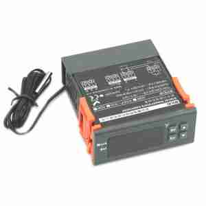
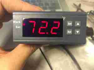
Pictures of the temperature regulator in my case it’s the knockoff WILHL WK7016F. The temperature probe looks waterproof and people have reported that it works fine submerged. If you’re concerned then simply seal the connection with some silicon. The orange clips on the side can be removed if you want, but they slide back and forth to secure the unit to a plastic case.
Step 2: Remove back plate
 Unscrew the screw holding the cover on the back of the controller with your Phillips screwdriver to reveal the terminal connections. There are some safety precautions one should take when working with electrical projects, like make sure nothing is plugged in. This isn’t a difficult project but take a few safety precautions.
Now depending on what model controller you bought the wiring diagram may be slightly different but they essentially all work the same. For me, ports 1 and 2 are the connections for the switch (which is what the controller turns on and off). These two ports are NOT powered.
Ports 3 and 4 are for power where you put in the power cord connected to a wall outlet. Ports 5 and 6 are Lock SW, which when you connect with a jumper wire, prevents the settings from being tampered with. Ports 7 and 8 connect to the temperature sensor which should already come installed.
Step 3: Wiring
 Prepare your wires by cutting your extension cord to the desired length and then twist the copper strands together to make then stronger. I soldered the tips as well because they stay in terminal blocks much better. This is called tinning and basically you twist the tips of the ends and run some solder onto them for strength and durability.
Cut and prepare the jumper wire that goes between ports 2 and 3. Even though AC appliances can be run either way, I am going to distinguish between the live (120V) and neutral (0V) lines. For those unfamiliar with AC currents, the small prong on your typical plug is live and the bigger prong is neutral.
Wire your unit according to the diagram provided and secure the wires in the terminal blocks using your flat head screw driver. You may end up using additional wire to extend or connect different parts.
Double check your wiring after you are done to make sure that you have properly connected everything. Carefully look over your wiring diagram and compare the diagram with what you have done. If all looks good proceed.
Step 4: Programming
 Now that everything is wired up, make sure your connections are secure and then plug the cord into the outlet. Your screen should now be reading ambient room temperature
Test the temperature sensor by holding it. It should rise fairly quickly to your body temperature.
There are four buttons on the controller: Set, Rst, Up, and Down
To turn the device on/off: hold Rst for 3 seconds to turn off and press Rst again to turn on
To set the temperature: press Set and then use the up and down arrows to set your temperature. Press Set again to exit.
To adjust more parameters: hold Set for 3 seconds, use up and down arrows to scroll through menus and press set to select parameter. Press Set to exit to parameter menu. Press Rst to exit to temperature display.
Parameters and their meanings
HC- Heat (H) or Cool (C). On heat if the temperature is below your set temperature it’ll power the load. On cool, if the temperature is over the set temperature it’ll power the load.
P7- Adjust time in minutes before load is powered. (i.e. if your temperature is set at 80, after reaching 80 degrees the controller will wait 1 minute before switching off load)
CA- Calibrate temperature probe. If you have a more accurate thermometer you can adjust the probe readings by +X degrees or -X degrees.
HS- High setting. Adjust the highest temperature value when setting your temperature.
LS- Low setting. Adjust the lowest temperature value when setting your temperature.
D- Differential threshold for activating the load. (i.e. if your set temperature is 80 and differential value is 1, then the load is triggered at 81)
I’ve set my values to the following:
Set temperature: 80F
HC: H
P7: 0
CA: 0
HS: 90F
LS: 60F
D: 0
By Neil Shieh
 Biotope One A Study of Flora and Fauna


